Ever stared at an electrical schematic and felt like you were deciphering ancient hieroglyphics? Those cryptic symbols for contactors and relays are more than just squiggles and boxes – they're the language of electrical control systems. Understanding them is key to wiring anything from a simple motor starter to complex industrial automation.
Imagine trying to build a LEGO castle without knowing which brick goes where. That's what it's like trying to wire a circuit without understanding contactor and relay symbols. These graphical representations are standardized shorthand for complex electrical components, allowing engineers and technicians to communicate clearly and efficiently.
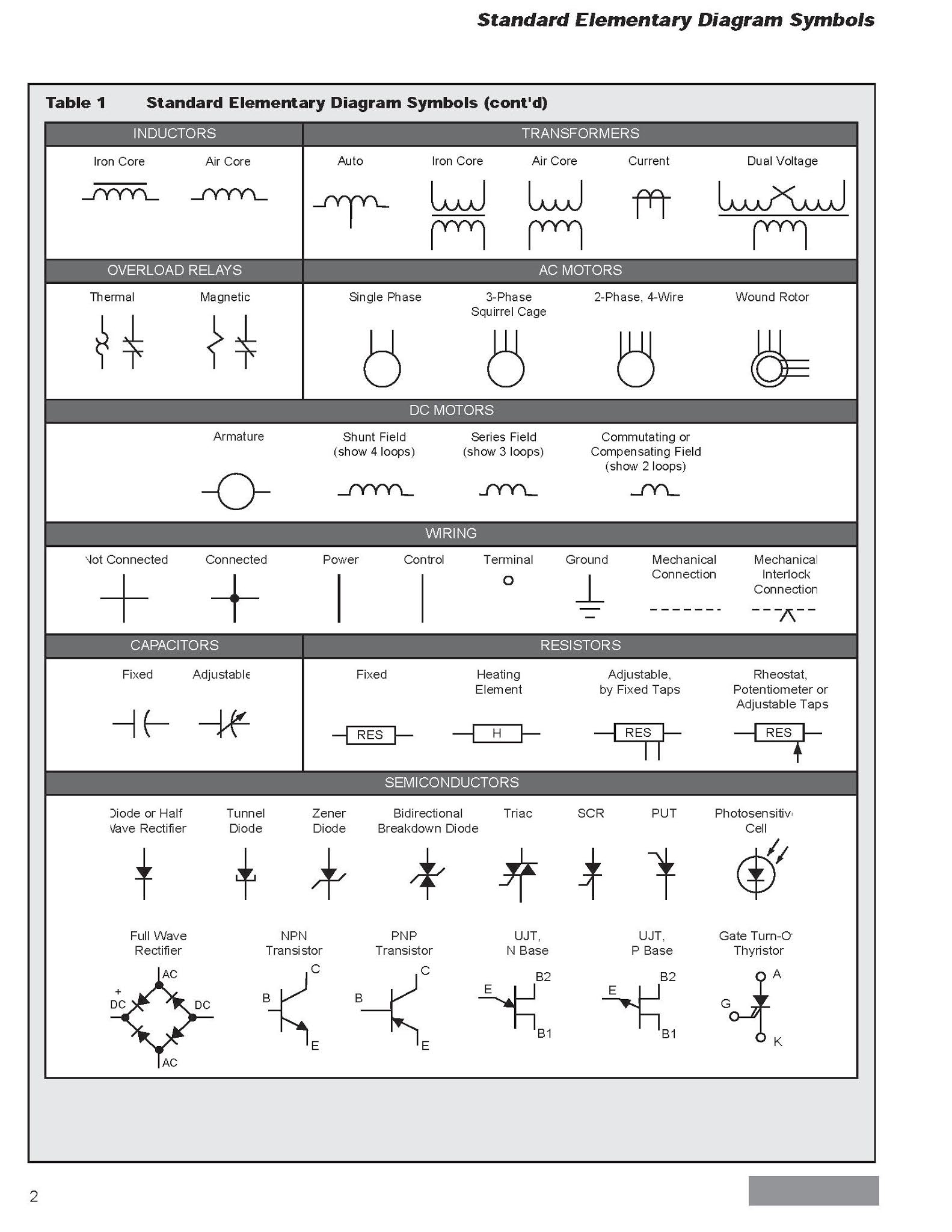
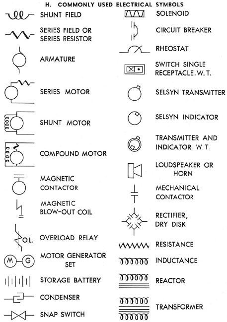
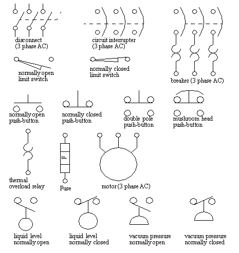
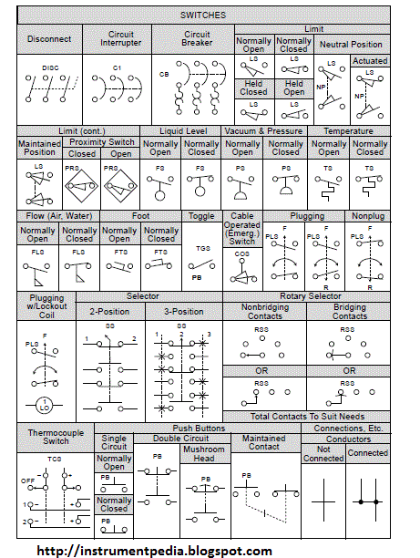
Contactor relay diagrams are the blueprints for controlling electrical power. These diagrams utilize specific symbols to represent the various components, including the contactors and relays themselves. These symbols, often standardized by organizations like IEC and NEMA, depict the function and connection points of each component. Mastering these symbols is like learning the alphabet of electrical control.
The symbols for these devices have evolved over time, driven by the need for clearer representation and international standardization. Early diagrams may have used more pictorial representations, while modern symbols are more abstract and focused on function. This evolution has made diagrams more concise and easier to understand across different engineering disciplines.
Misinterpreting a contactor relay symbol can lead to disastrous consequences. Imagine wiring a safety system incorrectly – the results could be dangerous. That's why accurate and standardized symbols are critical. They provide a universal language that ensures everyone involved in a project is on the same page.
A contactor is essentially a heavy-duty relay designed to switch large currents. Its symbol usually depicts a coil and a set of contacts. A relay, on the other hand, is used for lower current applications and its symbol is often simpler, focusing on the switching function. Different contact types, like normally open (NO) and normally closed (NC), are also represented by distinct symbol variations. Understanding these variations is crucial for interpreting circuit behavior.
One benefit of using standardized symbols is improved communication. Everyone, from the designer to the technician on the shop floor, can understand the diagram. This reduces errors and speeds up troubleshooting. Another benefit is efficient design. Symbols allow engineers to quickly and easily visualize complex circuits, optimizing the design process. Finally, standardized symbols enable easier documentation and maintenance. Diagrams using these symbols are clearer and easier to update, reducing downtime and improving system reliability.
To effectively use contactor relay symbols, start by familiarizing yourself with the basic symbols for contacts, coils, and other components. Then, practice reading simple diagrams and gradually progress to more complex ones. Online resources, textbooks, and software tools can help you learn and practice.
Advantages and Disadvantages of Standardized Contactor Relay Symbols
| Advantages | Disadvantages |
|---|---|
| Clear communication | Initial learning curve |
| Efficient design | Can be abstract for beginners |
| Easier documentation | Requires reference material for less common symbols |
Best Practices for using contactor relay symbols include: adhere to established standards (IEC, NEMA), clearly label all components, maintain consistency throughout the diagram, use software tools for complex diagrams, and regularly review and update diagrams as needed.
Real-world examples include: motor control circuits in industrial automation, HVAC systems, and safety interlock circuits. Challenges in using these symbols can include misinterpreting complex diagrams, keeping up with evolving standards, and ensuring consistency across different design platforms. Solutions include using symbol libraries in design software, regular training, and peer review of diagrams.
FAQ: What is a contactor? What is a relay? What is the difference between NO and NC contacts? What are the main components of a contactor? How are contactors used in motor control circuits? Where can I find resources to learn more about contactor relay symbols? What software can I use to create contactor relay diagrams? How do I interpret complex contactor relay diagrams?
Tips and tricks for using contactor relay symbols include using color-coding for different voltage levels, clearly marking terminal connections, and adding annotations to explain complex logic.
In conclusion, understanding electrical symbols for contactor relays is essential for anyone working with electrical control systems. These symbols are the language of electrical diagrams, enabling clear communication, efficient design, and easier maintenance. Mastering these symbols empowers you to effectively interpret and design complex circuits, from simple motor starters to sophisticated automation systems. Start learning today and unlock the power of electrical control. While there might be a slight learning curve initially, the long-term benefits of using standardized symbols far outweigh any initial challenges. Invest in your electrical knowledge, explore the resources available, and embrace the world of contactor relay symbols. It's a journey well worth taking, one that will equip you with the skills needed to navigate the fascinating world of electrical control.
The phenomenon of the little chick pio exploring zenons farm
Elevate your kitchen with sherwin williams creamy cabinets
Is bert kreischer married
Electrical Schematic Symbol For Relay - Khao Tick On
Timer Relay Working Principle Pdf at Thomas Mendoza blog - Khao Tick On
DIAGRAM Electrical Diagram Symbols Contactor - Khao Tick On
Electrical Single Line Diagram Symbols - Khao Tick On
electrical symbols for contactor relay - Khao Tick On
Identify The Nema Symbols - Khao Tick On
electrical symbols for contactor relay - Khao Tick On
Schematic Symbol Of Relay - Khao Tick On
Electrical Diagram Symbols Relay - Khao Tick On
Magnetic Contactor Autocad Symbol - Khao Tick On
Wiring Diagram For Motor Starter 3 Phase Controller Failure Relay - Khao Tick On
electrical symbols for contactor relay - Khao Tick On
Electrical Symbols For Relays Wiring Diagrams - Khao Tick On
Electrical Contactor Schematic Symbols - Khao Tick On
Electrical Symbols For Contactor Relay - Khao Tick On


