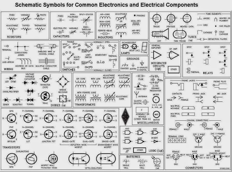
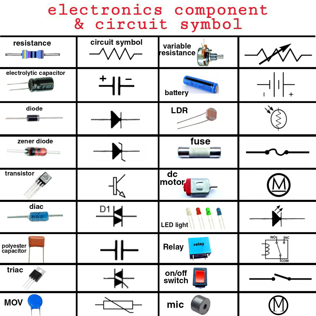
Understanding the language of electronics is crucial for anyone working with circuits and electronic devices. At the heart of this language lie the symbols representing various electronic components. These symbols are the building blocks of circuit diagrams, providing a visual shorthand for complex electronic systems.
Electronic component symbols are standardized graphical representations of electronic components used in circuit diagrams. They allow engineers and technicians to communicate circuit designs efficiently and accurately. Without a standardized set of symbols, deciphering complex electronic systems would be incredibly difficult, leading to confusion and potential errors.
Imagine trying to describe a complex circuit using only words. It would be a tedious and error-prone process. Electronic component symbols offer a concise and universally understood way to represent each component, making circuit design and analysis much simpler. From basic components like resistors and capacitors to more complex integrated circuits, each symbol conveys essential information about the component's function and characteristics.
This comprehensive guide aims to delve into the world of electronic component symbols, exploring their history, significance, and practical applications. We will cover a wide range of components, providing clear definitions, explanations, and examples to help you master the art of reading and interpreting circuit diagrams.
Whether you're a student just starting out in electronics, a hobbyist tinkering with circuits, or a seasoned professional, understanding electronic component symbols is essential for success. This guide will equip you with the knowledge you need to navigate the intricate world of electronics and unlock its vast potential.
The history of electronic component symbols is intertwined with the development of electronics itself. As new components were invented, the need for standardized symbols arose. Early symbols were often simple pictorial representations of the component's physical appearance. Over time, these symbols evolved into more abstract forms, optimized for clarity and ease of use. Organizations like the IEEE (Institute of Electrical and Electronics Engineers) and IEC (International Electrotechnical Commission) play a crucial role in standardizing these symbols, ensuring global consistency.
The primary issue related to electronic component symbols is the potential for confusion if not properly standardized. Different symbols can sometimes represent the same component, especially in older diagrams or those from different regions. This highlights the importance of adhering to recognized standards like those established by the IEEE and IEC.
A resistor, symbolized by a zig-zag line, limits current flow. A capacitor, represented by two parallel lines, stores electrical energy. A diode, symbolized by a triangle and a line, allows current flow in only one direction. Transistors, represented by more complex symbols, amplify or switch electronic signals.
Benefits of standardized electronic component symbols include clear communication, simplified circuit design, and easier troubleshooting. For example, a universal symbol for a capacitor allows engineers worldwide to understand its function within a circuit, regardless of language barriers.
Creating a successful circuit design involves selecting appropriate components, connecting them correctly according to the schematic diagram, and testing the circuit's functionality. Understanding component symbols is crucial throughout this process.
Advantages and Disadvantages of Standardized Electronic Component Symbols
| Advantages | Disadvantages |
|---|---|
| Clear Communication | Potential for Confusion with Older or Non-Standard Symbols |
| Simplified Circuit Design | Requires Learning a Set of Symbols |
| Easier Troubleshooting |
Best practices include using standard symbols, labeling components clearly, and ensuring consistency throughout the diagram. These practices enhance clarity and minimize errors in design and analysis.
Real-world examples include the use of component symbols in circuit diagrams for smartphones, computers, and televisions. Every electronic device relies on these symbols to guide its design and assembly.
One challenge is the sheer number of symbols to learn. The solution is to focus on the most common components first and gradually expand your knowledge. Another challenge is keeping up with new symbols as technology evolves. Online resources and industry publications can help address this.
FAQ: What is the symbol for a resistor? (Zig-zag line). What is a capacitor? (Stores electrical energy). What does a diode do? (Allows one-way current flow). What is a transistor? (Amplifies or switches signals). What are integrated circuits? (Complex circuits on a single chip). How do I learn electronic component symbols? (Study resources, practice reading diagrams). Where can I find a comprehensive list of symbols? (IEEE and IEC standards). What is the importance of standardized symbols? (Clear communication, efficient design).
Tips: Use flashcards to memorize symbols. Practice drawing circuit diagrams. Refer to online resources and textbooks. Join online forums and communities.
In conclusion, electronic component symbols are the fundamental language of electronics, enabling engineers and technicians to design, analyze, and troubleshoot complex circuits. From the simple resistor to the intricate integrated circuit, each symbol represents a crucial element in the world of electronics. Understanding these symbols is not just a skill; it's a key that unlocks the door to innovation and technological advancement. By mastering these symbols, you embark on a journey to understand the very fabric of modern technology, from the smartphones in our pockets to the sophisticated systems that power our world. So, delve into the world of electronic component symbols, embrace the challenge, and unlock the endless possibilities that await. Continue learning, exploring, and experimenting, and you'll be well on your way to mastering the language of electronics and contributing to the future of technology.
Navigating bank rakyats death benefit scheme
Cracking the code decoding nyt crossword drain clues
Building connections through shared manga experiences
Electronic Components Symbols And Functions - Khao Tick On
all electronics components symbols - Khao Tick On
Basic Components Of Circuit - Khao Tick On
Symbols On An Electrical Schematic - Khao Tick On
Electrical Circuit Symbols Pdf - Khao Tick On
Free Electronic Schematics And Circuits - Khao Tick On
Basic Electrical and Electronic Symbols - Khao Tick On
Components Of Circuit Diagram - Khao Tick On
Table Of Common Electronics Wiring Symbols - Khao Tick On
All Electronic Schematic Symbols - Khao Tick On
Circuit Components And Their Symbols - Khao Tick On
Electrical Electronic Symbols A Basic Introduction With Chart - Khao Tick On
Electronic Circuit Components Symbols - Khao Tick On
Table Of Common Electronics Wiring Symbols - Khao Tick On
Electronics Components List With Name - Khao Tick On


.jpg)


