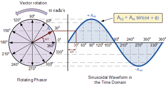
Imagine trying to analyze a complex AC circuit filled with fluctuating sinusoidal voltages. It can feel overwhelming! But what if there was a simpler way? That's where phasor representation comes in. Converting sinusoidal voltages to phasors is like having a secret decoder ring for AC circuits, unlocking easier analysis and understanding.
This powerful technique simplifies complex calculations involving sinusoidal voltages. By transforming these time-varying signals into static phasor quantities, we can replace tedious trigonometric calculations with simpler algebraic operations. This isn't just about making math easier; it's about fundamentally changing how we approach AC circuit analysis.
Sinusoidal voltages are the backbone of AC circuits, representing the oscillating nature of the electrical energy. But these sinusoidal functions, with their time-dependent nature, make circuit analysis challenging. Phasors provide a elegant solution by representing these sinusoidal voltages as complex numbers, capturing both magnitude and phase information.
The concept of representing sinusoidal quantities with phasors emerged from the need to simplify the analysis of AC circuits. Early electrical engineers recognized the complexities of working with sinusoidal functions directly and sought a more efficient method. The development of phasor representation revolutionized AC circuit analysis, enabling engineers to design and analyze complex power systems.
Converting a sinusoidal voltage to its phasor equivalent involves extracting the amplitude and phase shift of the sinusoid. The amplitude becomes the magnitude of the phasor, and the phase shift becomes the angle of the phasor. This representation allows us to work with complex numbers in a steady-state AC circuit analysis, simplifying calculations significantly.
Phasor representation allows us to analyze circuits in the frequency domain, rather than the time domain, which dramatically simplifies the mathematical process. For example, instead of dealing with differential equations, we can use simple algebraic equations to analyze circuits with capacitors and inductors.
Representing sinusoidal quantities as phasors allows us to visualize the relationship between voltage and current in AC circuits more easily. Phasor diagrams provide a graphical representation of these relationships, helping us understand the phase differences and magnitudes of different circuit elements.
Phasor domain circuit analysis is widely used in power systems analysis, allowing engineers to study the behavior of large-scale electrical grids. It also plays a critical role in designing electrical machines, control systems, and communication systems.
A simple example is representing the voltage v(t) = Vmcos(ωt + θ) as a phasor V = Vm∠θ. This conversion captures the essential information about the sinusoidal voltage without the explicit time dependence. This simplification makes it much easier to perform circuit calculations.
A step-by-step guide to convert a sinusoidal voltage to its phasor equivalent: 1) Identify the amplitude (Vm) and phase angle (θ) of the sinusoidal voltage. 2) Represent the phasor as Vm∠θ in polar form or as a complex number in rectangular form using Euler's formula.
Advantages and Disadvantages of Phasor Representation
| Advantages | Disadvantages |
|---|---|
| Simplifies AC circuit calculations | Only applicable to steady-state sinusoidal signals |
| Provides a clear visual representation of circuit behavior | Does not provide information about transient behavior |
| Facilitates analysis of complex power systems | Requires understanding of complex numbers |
Best Practices:
1. Always ensure that the frequency of all sources in the circuit is the same before applying phasor analysis.
2. Double-check the phase angles when converting sinusoidal voltages to phasors.
3. Use phasor diagrams to visualize the relationship between voltages and currents.
4. Remember that phasor analysis applies only to steady-state conditions.
5. Verify your phasor-domain results using time-domain analysis if necessary.
Frequently Asked Questions:
1. What is a phasor? A phasor is a complex number representing a sinusoidal function.
2. Why use phasors? They simplify AC circuit analysis.
3. How to convert a sinusoidal voltage to a phasor? Extract the amplitude and phase angle.
4. What are the limitations of phasor analysis? It's limited to steady-state sinusoidal signals.
5. What are the applications of phasors? Power systems analysis, electrical machine design, etc.
6. What is the relationship between phasors and complex numbers? Phasors are represented using complex numbers.
7. How do phasors simplify calculations? They replace trigonometric functions with algebraic operations.
8. What is a phasor diagram? A visual representation of phasors in a circuit.
Tips and Tricks:
Using software tools or online calculators can expedite phasor conversions and circuit calculations.
In conclusion, mastering the conversion of sinusoidal voltage to phasor representation is an essential skill for anyone working with AC circuits. This technique significantly simplifies circuit analysis and opens the door to understanding complex power systems, designing electrical machines, and developing control systems. While there are certain limitations, the advantages of using phasors far outweigh the drawbacks. By embracing this powerful tool, you gain a deeper understanding of the electrical world around us and equip yourself with the ability to solve challenging electrical engineering problems. Start practicing with phasor conversions today and unlock the secrets of AC circuit analysis! Explore resources online and in textbooks to further your understanding of this essential concept.
Why were obsessed with a picture of cat staring
Unlocking the potential tai industries ltd share price analysis
Unmasking the mystery how old is lil tony rapper
Phasor Diagrams For Ac Circuits - Khao Tick On
RC Circuit Phasor Diagram - Khao Tick On
sinusoidal voltage to phasor - Khao Tick On
sinusoidal voltage to phasor - Khao Tick On
Schneider Electric Phasor Diagram - Khao Tick On
The Current In An Inductive Circuit - Khao Tick On
DIAGRAM Purely Capacitive Circuit Phasor Diagram - Khao Tick On
sinusoidal voltage to phasor - Khao Tick On
Meaning Of Purely Resistive at Beverly Eisenbarth blog - Khao Tick On
Phasor Diagram Of Rc Series Circuit - Khao Tick On
sinusoidal voltage to phasor - Khao Tick On
Phasor Diagrams Of Ac Circuits - Khao Tick On
Locus Diagram Of Series Rlc Circuit - Khao Tick On
Phase Diagram Of Lr Circuit - Khao Tick On
Phasor Diagram Rlc Circuit Series - Khao Tick On


