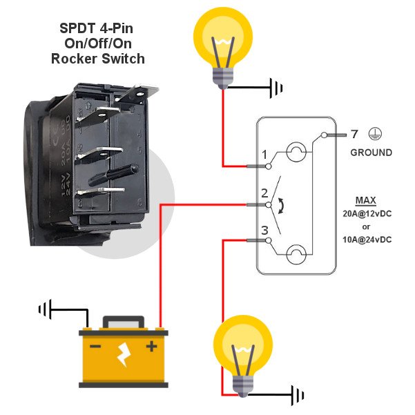
Ever wondered how a simple flick of a switch can control two separate circuits simultaneously? The answer lies within the ingenious design of the Double-Pole, Single-Throw (DPST) toggle switch. These compact powerhouses are essential components in various electrical systems, enabling simultaneous control over two distinct circuits. This article delves into the intricacies of DPST toggle switch configurations, offering a comprehensive guide to understanding their functionality, wiring, and applications.
Understanding the electrical schematic, or the DPST toggle switch wiring diagram, is crucial for correctly implementing these switches. The diagram acts as a roadmap, guiding you through the connections between the switch terminals and the circuits they control. Without a proper understanding of this diagram, you risk incorrect wiring, potentially leading to malfunctions or safety hazards.
DPST toggle switches find applications in a wide array of devices, from simple household appliances to complex industrial machinery. Their ability to control two circuits independently makes them ideal for scenarios requiring synchronized operation. Imagine controlling both a light fixture and a fan with a single switch – this is the power of a DPST toggle switch. These switches provide a streamlined and efficient solution for managing multiple circuits.
The core concept behind the DPST toggle switch lies in its two sets of contacts. Each set acts as a bridge, connecting or disconnecting a specific circuit. When the switch is toggled, both sets of contacts move simultaneously, either making or breaking the connection for both circuits. This synchronized action is what sets the DPST switch apart from its single-pole counterpart, the SPST switch, which controls only one circuit.
Exploring the intricacies of DPST toggle switch connections is vital for ensuring proper functionality. Understanding the pole and throw terminology is essential. "Pole" refers to the number of separate circuits the switch can control, while "throw" indicates the number of positions the switch can adopt. A DPST switch, therefore, has two poles (controlling two circuits) and a single throw (on or off).
Historically, toggle switches emerged as a more robust alternative to knife switches. Their simple yet reliable mechanism made them popular in various applications. Over time, the DPST variant gained prominence due to its enhanced control capabilities. The significance of understanding the DPST toggle switch connection diagram cannot be overstated. A correctly wired switch ensures safe and predictable circuit operation.
A DPST toggle switch wiring diagram typically depicts the switch with four terminals: two for each pole. Connecting the power source and the loads correctly to these terminals is essential for proper functioning. An example would be using a DPST switch to control two separate lights in a room, allowing you to turn both on or off with a single switch.
Benefits of using DPST toggle switches include simplified wiring for controlling two circuits, reduced component count, and increased control flexibility. For instance, you can wire a DPST switch to turn on a light and a motor simultaneously, streamlining the operation of a machine.
To correctly connect a DPST toggle switch, follow these steps: 1) Identify the switch terminals and the circuits they will control. 2) Connect the incoming power supply to the appropriate terminals. 3) Connect the loads (e.g., lights, motors) to the remaining terminals, following the wiring diagram. 4) Test the circuit to ensure proper operation.
Advantages and Disadvantages of DPST Toggle Switches
| Advantages | Disadvantages |
|---|---|
| Controls two circuits simultaneously | More complex wiring than SPST switches |
| Simplified wiring for dual-circuit control | Not suitable for controlling three or more circuits independently |
Best practices include using appropriately sized wiring, ensuring secure connections, and double-checking the wiring diagram. Always consult a qualified electrician if you are unsure about any aspect of the installation process.
Real-world examples include using DPST switches in staircase lighting, controlling garage door openers, and operating power tools with safety interlocks.
Challenges can include incorrect wiring leading to malfunctions, loose connections causing intermittent operation, and switch failure due to overload. Solutions involve careful wiring, regular maintenance, and using appropriate circuit protection.
FAQs: What does DPST stand for? (Double-Pole, Single-Throw) How many circuits can a DPST switch control? (Two) ... (Add more FAQs)
Tips: Always disconnect the power supply before working on electrical circuits. Use wire nuts for secure connections. Label the wires for easier troubleshooting.
In conclusion, DPST toggle switches are versatile components essential for numerous electrical applications. Mastering the intricacies of the DPST toggle switch wiring diagram empowers you to safely and effectively control multiple circuits, simplifying wiring and enhancing functionality. From household appliances to industrial machinery, DPST switches play a vital role in streamlining circuit control. By understanding their operation, benefits, and best practices for implementation, you can harness the power of these compact switches to optimize your electrical systems. Always prioritize safety and consult qualified professionals for complex electrical work. Take control of your circuits with the power of DPST toggle switches!
Unlocking your dream home with behr paint colors
Crafting meaningful recognition exploring certificate border frames
Spelling out numbers in spanish the art of writing 25 veinticinco
Dpst Switch Wiring Diagram - Khao Tick On
Spdt Switch Wiring Explained - Khao Tick On
dpst toggle switch wiring diagram - Khao Tick On
Dpdt 8 Pin Toggle Switch Wiring Diagram - Khao Tick On
4 Pin Rocker Switch Wiring Diagram Database Wiring Diagram Sample - Khao Tick On
Dpdt Reversing Switch Diagram - Khao Tick On
dpst toggle switch wiring diagram - Khao Tick On
Illuminated Dpdt Switch Wiring Diagram - Khao Tick On
How to wire a DPST toggle switch step - Khao Tick On
Ridgid 300 Switch Wiring Diagram Collection - Khao Tick On
Rf Switch Dpdt Switch Wiring Diagram - Khao Tick On
On off on toggle switch wiring diagram - Khao Tick On
Dpst Switch Circuit Diagram - Khao Tick On
4 Pin Dpst Switch Wiring Diagram - Khao Tick On
Generac 200 Amp Transfer Switch Wiring Diagram Download - Khao Tick On


